
Using the Emulator
Clock and Reset
A clock pulse can be triggered by clicking the Clock button. That pulse is sent to all hardware components as well as emulated ones. Clicking Reset sets the emulator back to your first instruction, like as if you had just opened the emulator.
Assembler and Microassembler
Clicking the Run Assembler or Run μAssembler buttons will run the assembler or microassembler. On Windows, a command prompt will appear which may ask you to generate a new UUID. This UUID is not the same UUID as used to connect the emulator to the photon, so say yes. Any errors in assembly will appear in those windows. At this time (v0.2.0-pre) you may have to close and reopen the emulator after performing either of these functions. See more about the Assembler and Microassembler on their docs pages.
Control Lines
Each component has its 8 control lines represented as checkboxes next to it. Hovering over a control line will show what you specified as its function, or “None” if there was nothing specified. A control line being checked means that it is high, not that it is asserted. Likewise a control line not being checked means that it is low, not that it is not asserted. On startup control lines are set to the control line active polarity (set in controlmap.json)
Increment Buttons
An increment button is present next to every component. Its inner value displays the current value of that component (may not be accurate if that component is marked as hardware). Clicking on the button will increment that component’s current value by one. You cannot increment a component that is marked as hardware.
Bus Indicators
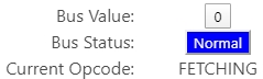
Above the components there are two buttons which represent the current bus value and the bus status of the emulator. (The bus value may not be accurate if the driving component is marked as hardware). Bus status shows whether the bus is floating (yellow), normal (being outputted to, blue), or in conflict (bus conflict, red). The current opcode is also displayed.
Menu Bar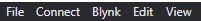
The menu bar contains 5 dropdown menus: File (on MacOS this is CPU Emulator), connect, blynk, edit, and view. Under connect there are two options: connect to photon, which allows you to set a UUID, and set hardware components, which allows selection of components that are present in hardware. Documentation about connecting to hardware is present on its doc.Under view, you can zoom in and out, go fullscreen, refresh (side effects to the emulator may occur) or open dev tools for debugging access. Under Blynk, there is an option to enter your Blynk API key. Under edit there is standard copy/paste/cut actions with keyboard shortcuts.
Configuration Files
The emulator uses multiple files to create your CPU. If these files are not properly created or configured, the emulator will likely run into issues and not produce desirable results.
controlmap.json
The control map is a JSON file that outlines each component and its properties.
Each component is a JSON object with the name of the object being the component name. Inside of each component you need to specify (at minimum): type, bits, bus position, control line active polarity (activePolarity), control line bit positions, and clear. See the chart on the next page. A sample PC is shown to the right.
Control Map Component Options
Component Option
Description
Type of value/acceptable values
type
What type of component is being created
“Register”, “PC”, “RAM”, “CTRL”, “ALU”, “MemoryAddressRegister”
bits
The size of the connection between the component and the bus
8, 16
busPosition
What bus position the component occupies
Positive Integer, no duplicates between components
activePolarity
What the polarities of each control line are
8 1s or 0s in a string. Example:
controlLinesBitPosition
Array of key value pairs representing the purpose of each control line.
Control Line Names:
OE, CLR, LOAD, INC, LOAD_LSB, LOAD_MSB, LOAD_16, RST, CF_OUT, ZF_OUT, FLG_OE, SUB, FLAGS_LOAD, WE, DONE, HALT

inputComponents
Array of components inputting to that component
Names of input components

clear
What control line will clear/reset the component
Integer between 0-7 representing a control line position
assemblerFile
Path to the assembled.o file generated by the assembler.
On Windows: ./assembler/assembled.o
On MacOS:
../../../assembler/assembled.o
microcodeFile
Path to the microcode.o file generated by the microassembler.
On Windows:
./microassembler/microcode.o
On MacOS:
../../../microassembler/microcode.o
opcodes.json
The OPcodes JSON file contains all of your instructions in your instruction set, and the microcode within them. These instructions can be referenced in code.asm
code.asm
The code.asm file contains your assembly code for your CPU. This file is used by the assembler to generate assembled.o
assembled.o
Generated by the assembler based off code.asm when you click “Run Assembler”
microcode.o
Generated by the microassembler based off opcodes.json when you click “Run µAssembler”
Last updated